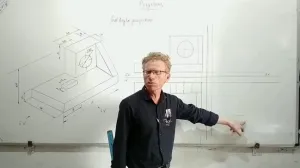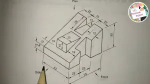

Dimensions :-
length :- 70mmView :-
hieght:- 50mm
width :- 50mm
0ther:- 15mm 20mm 10mm 30mm 10mm 50mm
VIews:-
front view :- 70*50mm
top view :-70*50mm
side view:- 50*50mm
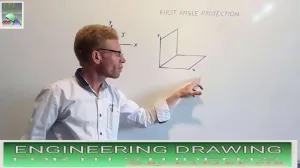
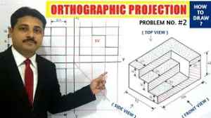
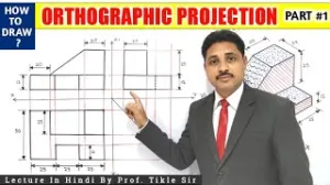
Drawing in First Angle Projection involves two primary conceptual and procedural steps to ensure the object is accurately represented according to international engineering standards:
1. Positioning the Object in the First Quadrant
According to the syllabus section on the "concept of axes plane and quadrant," First Angle Projection requires the draughtsman to imagine the object placed in the first quadrant. In this theoretical system, the object is situated between the observer and the plane of projection. This means that when you look at the object, you project its features forward onto the "wall" (the vertical plane) or downward onto the "floor" (the horizontal plane).
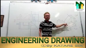
2. Arranging the Multi-Views (Standard Layout)
Once the views are projected, they must be arranged on the drawing sheet in a specific, standardized relationship. Based on the concept of orthographic projection described in the sources, the views are placed as follows:
- Front View: This is the primary view, typically drawn in the upper section of the sheet.
- Top View (Plan): Unlike other projection methods, in First Angle Projection, the top view is projected and drawn directly below the Front View.
- Side Views: These views are "reversed" in their placement; for example, the view seen from the left side of the object is drawn on the right side of the Front View.
To verify that the drawing is in First Angle, the Projection Symbol (two concentric circles beside a cone frustum) must be included in the "PROJECTION" box of the title block.


 ,
,  ,
, 

 ,
, 
 ,
,