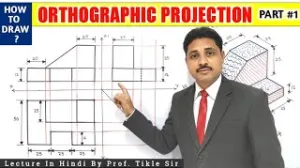

FIRST ANGLE PROJECTION 4 EXAM. Q JAN.2017 THIS VIDEO DESCRIBE ORTHOGRAPHIC VIEW IN FIRST ANGLE PROJECTION BY CHETAN WANODE
To draw an object using First Angle Projection based on the engineering principles and exercises found in the sources, you should follow these procedural steps:
1. Preparation and Sheet Layout
- Sheet Selection: Begin with an A3 or A4 size drawing sheet.
- Border and Title Block: Draw standard margins/borders and a title block in the bottom right corner.
- Projection Symbol: Within the title block, you must include the specific First Angle Projection symbol. This symbol depicts two concentric circles placed beside the side view of a cone frustum (where the smaller end of the frustum is closer to the circles).
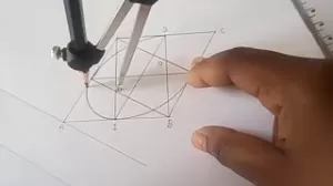
2. Arranging the Views
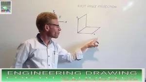
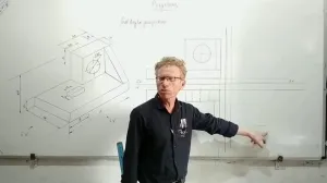
First Angle Projection is based on the concept of the object being in the first quadrant. The views must be arranged in the following standardized positions:
- Front View: This is the primary view drawn in the upper section of your drawing space.
- Top View (Plan): Project this view directly below the Front View.
- Side Views: In First Angle Projection, the views are "flipped." For example, the Right Side View is drawn on the left side of the Front View.
3. Application of Line Types
Using the correct "alphabet" of lines is essential for technical accuracy:
- Continuous Thick Lines (0.5 mm): Use these for all visible outlines and edges of the object.
- Continuous Thin Lines (0.2 mm): Use these for projection (extension) lines and dimension lines.
- Dashed Lines: Use these to define hidden outlines and edges that are not visible from the outside.
- Chain Thin Lines: Use these for center lines and lines of symmetry.
4. Dimensioning the Drawing
Once the views are drawn, you must indicate measurements using one of two methods:
- Aligned System: Place dimensional values parallel to and above the dimension lines. They should be readable from the bottom and the right side of the sheet.
- Unidirectional System: All dimensional values are placed such that they can be read from the bottom of the drawing sheet only. Non-horizontal dimension lines are interrupted in the middle for the value.
5. Finishing Touches
- Lettering: Use single-stroke capital letters (standard height often 10 mm for headings) for any notes or view titles.
- Cleaning: Remove any unnecessary construction lines or marks using an eraser or an erasing shield to avoid damaging the final drawing.
 ,
,  ,
, 


 ,
, 


 ,
, 


 ,
,