Skip to header Skip to main navigation Skip to main content Skip to footer

User account menu

  • Log in
Home
ITI Engineering Drawing
ITI Engineering Drawing – Complete Study Guide

Main navigation

  • Home
  • Article
  • ED Syllabus
  • Video
  • Question Paper
  • Sign and Symbols
  • Employability Skills (opens in new tab)
  • Hunnarbaaz (opens in new tab)
  • ITI Tools (opens in new tab)
  • Syllabus (opens in new tab)
  • Workshop Calculation and Science (opens in new tab)

How to draw in first angle projection 6 first angular projection

Breadcrumb

  • Home
  • Video
  • How to draw in first angle projection 6 first angular projection
By iti | 3:48 PM IST, Sat November 15, 2025

To draw an object using First Angle Projection according to standard engineering practices described in the sources, follow these procedural steps:

1. Preparation of the Drawing Sheet

Begin by selecting a standard A3 or A4 size drawing sheet. You must mark the margins (borders) and draw a title block in the right-side bottom corner. The title block must include a dedicated "PROJECTION" section where you draw the First Angle Projection symbol: two concentric circles placed next to the side view of a cone frustum.

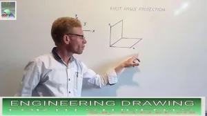
2. Conceptual Layout (Quadrant System)

The theory of First Angle Projection is based on the concept of the axes plane and quadrant, where the object is imagined to be placed in the first quadrant. This determines how the views are projected onto the paper:

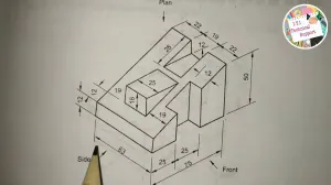
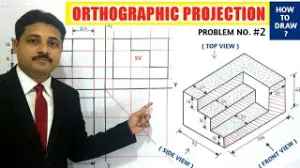
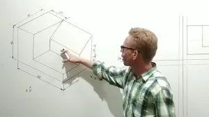
  • Front View: This is your primary view, drawn in the upper portion of the sheet.
  • Top View (Plan): In First Angle Projection, the top view is projected directly below the front view.
  • Side Views: The views are "inverted" in position; for instance, the view from the left side of the object is drawn to the right of the front view.

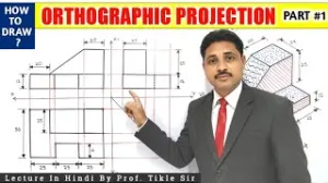
3. Drafting Visible and Hidden Features

Using instruments like the mini-drafter for accuracy, begin drawing the outlines of the views.

  • Visible Edges: Use continuous thick lines (typically 0.5 mm) for all visible outlines and edges.
  • Hidden Features: Use dashed lines to represent edges or outlines that are not visible from the exterior.
  • Center Lines: Apply chain thin lines to indicate axes of symmetry or centers of circles.

4. Applying Dimensions

Once the views are outlined, indicate measurements using one of two standard systems:

  • Aligned System: Place dimensional values parallel to the dimension lines, readable from the bottom or the right side of the sheet.
  • Unidirectional System: Place all values so they are readable only from the bottom of the sheet, interrupting non-horizontal dimension lines in the middle for the value.

5. Lettering and Numbering

Add necessary notes and view titles using single-stroke capital letters. For headings, a height of 10 mm is standard. Use a medium-hard pencil (Grade H) to ensure the letters are clear and legible.

6. Final Review and Cleaning

Check the drawing for uniformity in line thickness and ensure all product features are correctly defined. Use an erasing shield to remove unnecessary construction lines without damaging the final visible lines. Finally, preserve the sheet in a suitable file for approval.

Book navigation

  • Isometric By E ITI SKILL

ITI ED Article

Protractor

Protractor

AT 594x841 , A2 420x594 , A2 297x420

Method of folding of printed drawing sheets as per BIS SP: 46-2003

french curve , french curve

French curves

Drawing board

Drawing instruments : Drawing board

Scales

Scales

Drop spring bow pencil and pen

Drop spring bow pencil and pen

, T’-squares-and-Drawing-instruments

Drawing instruments : ‘T’ Square

Inking pen or liner or ruling pen

Inking pen or liner or ruling pen

Drawing Instruments

Drawing Instruments - box and pencils

Lengthening bar

Lengthening bar

Engineering drawing sheets

Set square

Set square

Main types of Engineering drawing:

Purpose of studying engineering drawing:

Large divider

बड़ा डिवाइडर (Large Divider)

Technical drawings

Large compass

Large compass

Importance of Engineering Drawing

Erasing shield

Drawing instruments : Erasing shield

One picture worth one thousand words

Video

प्रथम कोणीय प्रक्षेप सिधांत
First Angle projection 5 Exam Q in Aug. 2017 one year trade
How to draw in First Angle Projection 4
First angle projection 7 Solid (hexagonal pyramid)
First Angle Projection 3
How to draw in first angle projection 6 first angular projection
ड्राइंग कैसे बनाएं First angle projection 2
इंजीनियरिंग ड्राइंग (स्क्रु थ्रेड)
How to draw orthographic projection in Hindi, iti drawing paper
ORTHOGRAPHIC PROJECTION IN ENGINEERING DRAWING IN HINDI (Part-2)
ORTHOGRAPHIC PROJECTION IN ENGINEERING DRAWING IN HINDI (Part-1)
first angle projection 8 प्रथम कोणीय प्रक्षेप किस तरह बनाया जाता है
FREE HAND ड्राइंग करते समय सावधानियां
MAKING OF PENTAGON| HEXAGONAL| HEPTAGON| OCTAGON
HOW TO MAKE Ellipse | #ellipse | #ENGINEERING DRAWING
Centre of a circle| Engineering drawing | वृत्त का केंद्र निकाले | ITI IN LUCKNOW
Hexagonal Nut | ITI ENGINEERING DRAWING | ITI IN LUCKNOW
HSI TRADE THEORY MODEL PAPER | ITI IN LUCKNOW
Employbility skill | Model paper | ITI ELECTRICIAN,FITTER | ITI IN LUCKNOW
LETTERING AND NUMBERING | ITI ENGINEERING DRAWING | ITI IN LUCKNOW

Common Subject

  • Engineering Drawing
  • Employability Skills
  • Workshop Calculation Science

Directory

  • Industrial Training Institutes
  • Engineering College
  • Medical College

All Syllabus

  • ITI Syllabus
  • CTS Syllabus
  • CITS Syllabus
  • Apprenticeship Training Scheme
  • Flexi MOU Syllabus
  • जन शिक्षण संस्थान Syllabus

Electrician + Wireman + Electroplater + Electrician Power Distribution + Lift and Escalator Mechanic | ITI Fitter | ITI COPA | ITI Welder | ITI Mechanic | ITI Electronics | Agriculture + Horticulture + Floriculture | ITI Draughtsman Civil & Mech | ITI Refrigeration & Air Conditioning | ITI Turner | ITI Plumber | ITI Machinist | ITI Cosmetology | ITI Sewing | ITI Surveyor

Copyright © 2026 ITI Directory - All rights reserved

Developed and Designed by ITI Directory