
This video has solved the question in the paper of Turner Trade in 2016
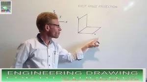
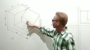
How to draw in First Angle Projection
Based on the syllabus and exercises provided in the sources, First Angle Projection is the third sub-topic listed under the "Concept and Reading of Drawing" section (Topic 5), specifically covered in Exercise 1.5.19.
The sources define this method through three primary components:
1. The First Quadrant Theory
First Angle Projection is based on the "concept of axes plane and quadrant". In this system, the object is imagined to be placed in the first quadrant of a four-quadrant system, positioned between the observer and the plane of projection.
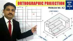
2. Standard Arrangement of Views
In First Angle Projection, the spatial relationship between views is standardized as follows:
- Front View: Drawn in the upper section of the drawing area.
- Top View (Plan): Projected directly below the front view.
- Side Views: The view from the left side of the object is drawn on the right side of the front view, and vice-versa.
3. Symbolic Representation in the Title Block
Technical drawings must explicitly state the projection method used to ensure correct interpretation by designers and craftsmen globally.
- Title Block Requirement: Standard layouts (specifically Title Block - 3) include a dedicated "PROJECTION" box.
- The Symbol: The First Angle Projection symbol consists of two concentric circles placed horizontally next to the side view of a cone frustum.
Drafting Standards
When drawing in First Angle Projection, the sources emphasize using the correct line types:
- Continuous Thick Lines (0.5 mm): Used for all visible outlines and edges.
- Dashed Lines: Used to represent hidden features or edges.
- Chain Thin Lines: Used for center lines and axes of symmetry.
 ,
,  ,
, 


 ,
, 


 ,
,