How to draw orthographic projection in Hindi, iti drawing paper
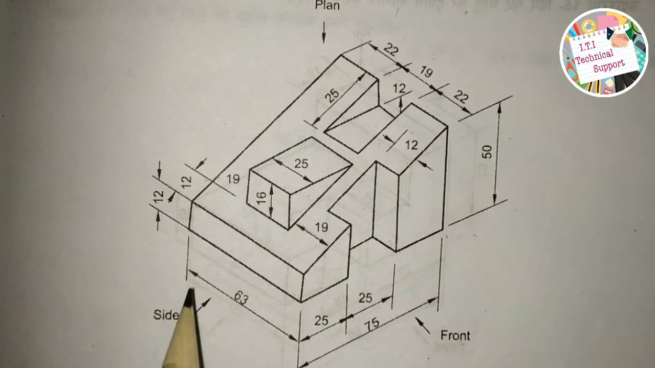
To draw an orthographic projection (also known as a multi-view drawing), you must transform a three-dimensional object into a series of two-dimensional views that accurately define its features, dimensions, and specifications.
Based on the engineering standards and examples in the sources, follow these steps to create an orthographic drawing:
1. Setup and Sheet Preparation
- Sheet Selection: Use a standard A3 or A4 size drawing sheet.
- Layout: Mark the borders (margins) and draw a title block in the bottom right corner.
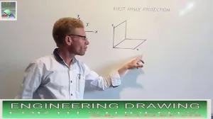
- Projection Symbol: Within the title block's "PROJECTION" box, indicate whether you are using First Angle or Third Angle projection by drawing the appropriate symbol (typically two concentric circles and a cone frustum).
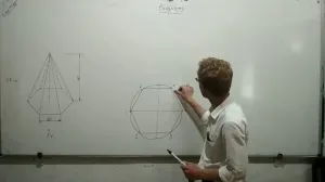
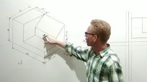
2. Selection of Views
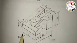
Identify the primary views necessary to fully describe the object. A standard set includes:
- Front View: The view showing the most detail or the object's primary orientation.
- Top View (Plan): The view looking down from above.
- Side View (End View): Usually the Right Side or Left Side view.
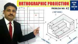
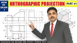
3. Positioning the Views (First Angle Standard)
The sources emphasize the concept of axes plane and quadrant. In First Angle Projection, which is the primary method taught in these exercises, the views are arranged as follows:
- Place the Front View in the upper section of the drawing space.
- Project the Top View directly below the Front View.
- Draw the Right Side View to the left of the Front View.
- Alignment: Ensure the views are perfectly aligned. The Front and Top views must share the same width, while the Front and Side views share the same height.
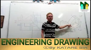
4. Drafting with the "Alphabet of Lines"
Technical drawings require specific line types to distinguish between different features:
- Visible Outlines and Edges: Use Continuous Thick Lines (0.5 mm).
- Hidden Features: Use Dashed Lines (thick or thin) to represent edges or outlines not visible from the exterior.
- Center Lines: Use Chain Thin Lines to indicate axes of symmetry or the centers of circular holes.
- Projection/Extension Lines: Use Continuous Thin Lines (0.2 mm) to project dimensions from one view to another.
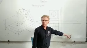
5. Dimensioning the Projection
Once the outlines are complete, apply dimensions using one of two standard systems:
- Aligned System: Place values parallel to and above the dimension line, readable from the bottom or right side.
- Unidirectional System: All values are placed to be read from the bottom of the sheet only, with non-horizontal dimension lines broken in the middle to insert the value.
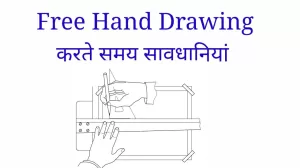
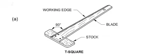
6. Finalizing with Instruments
Use a mini-drafter or T-square and set-squares to ensure all lines are perfectly horizontal, vertical, or at the correct angle. For curved features that cannot be drawn with a compass, use French curves to ensure a smooth finish. Finally, use an erasing shield to remove construction lines without damaging the final orthographic views.
 ,
,  ,
, 
 ,
, 


 ,
, 


 ,
,