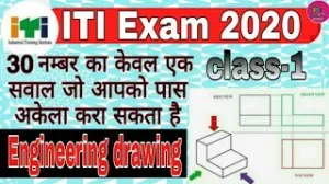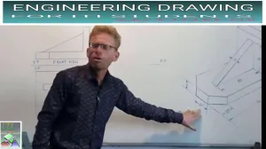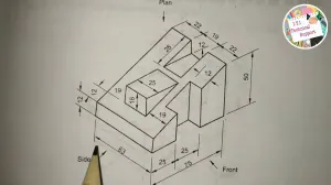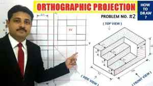
THIS IS THE 2ND VIDEO ON "ORTHOGRAPHIC PROJECTIONS". TODAY WE WILL STUDY 2ND PROBLEM OF ORTHOGRAPHIC PROJECTION.
Orthographic projection is a fundamental method used in technical drawings to represent a three-dimensional object in two dimensions by using multiple views. It is considered a "universal language" for engineers and craftsmen, ensuring that a design created by one person can be accurately interpreted and manufactured by another, regardless of nationality.
1. Core Concept and Multi-Views
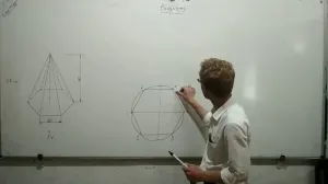
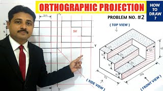
In orthographic projection, an object is viewed from different directions—typically at right angles to its surfaces—to create a "multi-view" drawing. The three primary views used to fully define an object's features and dimensions are:
- Front View: The primary view showing the most detail or characteristic shape.
- Top View (Plan): The view seen from directly above the object.
- Side View (End View): Usually the Right Side or Left Side view, showing the object’s depth and height.
2. The Quadrant System
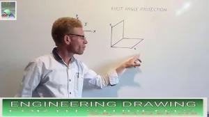
The theory of orthographic projection is based on the "concept of axes plane and quadrant". The space is divided into four quadrants by horizontal and vertical planes. The two standardized methods used globally are based on which quadrant the object is imagined to be in:
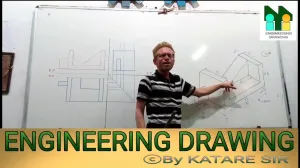
- First Angle Projection: The object is imagined in the first quadrant, placed between the observer and the plane of projection. This results in the Top View being drawn below the Front View, and the Right Side View being drawn on the left of the Front View.
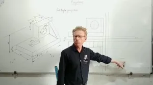
- Third Angle Projection: The object is imagined in the third quadrant, where the plane of projection is between the observer and the object.
Technical drawings must include a projection symbol in the "PROJECTION" box of the title block (consisting of concentric circles and a cone frustum) to specify which method was used.
3. Drafting Standards and Lines
To correctly define product features, orthographic projections use a specific "alphabet" of lines:
- Continuous Thick Lines (0.5 mm): Used for all visible outlines and edges.
- Dashed Lines: Represent hidden outlines and edges not visible from the exterior of that specific view.
- Chain Thin Lines: Used for center lines and lines of symmetry.
- Continuous Thin Lines (0.2 mm): Applied for extension and dimension lines to project measurements between views.
4. Drawing Instruments
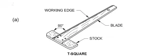
For accuracy and speed, a mini-drafter is the most important device used to create these projections. It combines the functions of a T-square, set square, protractor, and scale, allowing for perfectly horizontal, vertical, and angled lines. Other essential tools include set squares (for 30°, 45°, and 60° angles) and French curves for smooth arcs that cannot be drawn with a compass.
5. Importance in the Syllabus
In the Engineering Drawing syllabus, orthographic projection is a major topic within the "Concept and Reading of Drawing" section. It typically requires 14 hours of study to master the definitions and differences between projection methods, which is essential for reading manufacturing and construction drawings used in industry.
 ,
,  ,
, 


 ,
, 


 ,
, 


 ,
,